 Intranet


 EAST experiment
EAST Diagnostic Data Acquisition System
2021-06-07 09:22
1. System Diagram
EAST diagnostic data acquisition system mainly collects the diagnostic signals from each diagnostic system, and transmits the diagnostic data to the data storage server, which provides data source for off-line analysis of researchers, and also includes the output function of other control signals. The system diagram is shown in Figure 1.
The whole data acquisition system includes the following parts:
1) Data acquisition subsystem
2) Acquisition console
3) Data storage server
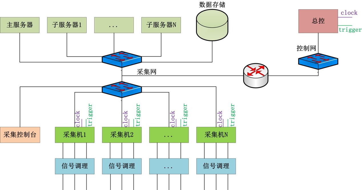
- Figure 1 Architecture of Data Acquisition System
2. System Function
The main functions of EAST diagnostic data acquisition system include:
1) Collect the physical diagnosis signal and provide a distributed acquisition subsystem with sampling rate from 1Hz to 1GHz;
2) Remote management and control of front-end signal conditioning equipment of diagnostic signal;
3) Realize the control signal output subsystem of PCS;
4) Manage and control the data acquisition subsystem;
5) Store the diagnosis data;
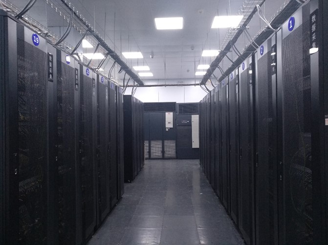
Figure 2 Data Acquisition System Room
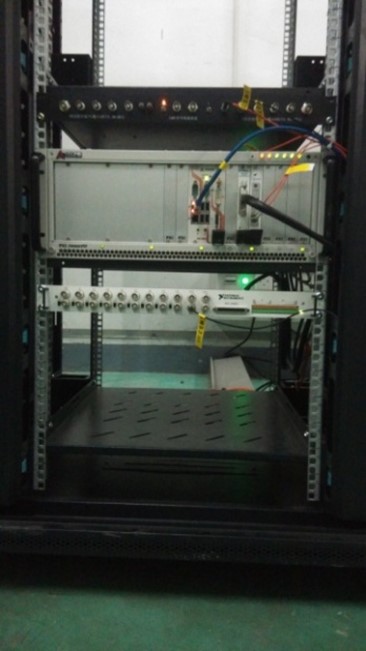
Figure 3 Data Acquisition Subsystem
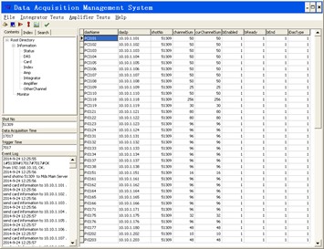
Figure 4 Data Acquisition Control Management Interface
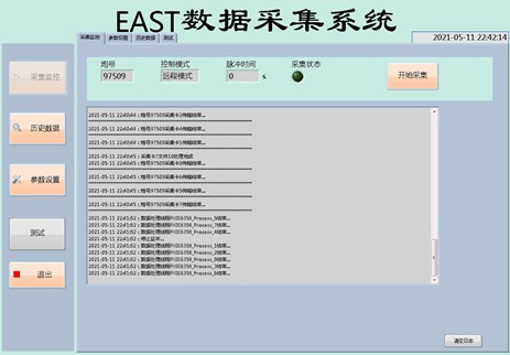
Figure 5 Data Acquisition Software HMI
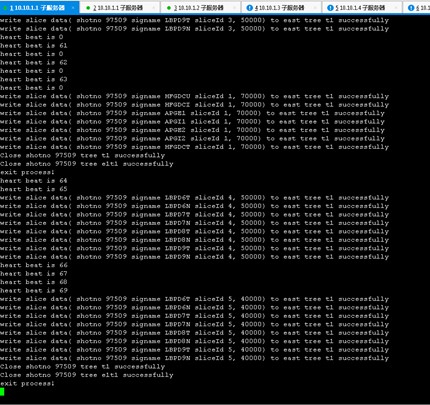
Figure 6 Data Storage Software Interface
3. System Improvement
- Improvement of hardware
- Upgrade the acquisition card and industrial computer of high frequency magnetic probe acquisition system
- Upgrade the front-end signal transfer module of electromagnetic measurement and acquisition system
- The channel of divertor acquisition system is expanded
- New Diagnostic Acquisition System
- A synchronous acquisition system with 144 channel and sampling rate 1.25MHz is placed on the first floor of EAST Hall
- A synchronous acquisition system with 128 channel and sampling rate 1 MHz is placed in the power supply room of divertor
- Two synchronous acquisition system with 16 channel and sampling rate 10 kHz are placed on the first floor and the first floor of EAST Hall
- A set of thermocouple acquisition system is added
- A set of data acquisition system for power supply of lower divertor
- Control Subsystem
- A set thermocouple acquisition system is added, and part of the temperature signal are used to generate four protection signal with limits through the optical fiber to NBI system
- A set control output subsystem for PCS is used to control power supply of lower divertor
4. System Distribution
At present, the acquisition subsystem is distributed around the EAST device, and the distribution diagram is shown in Figure 7.

Figure 7 Distribution of Data Acquisition Subsystem
5. Operation Parameters
1) Number of data acquisition subsystem: 62
2) Number of acquisition channels: 4035
3) Sampling rate: 1 Hz ~ 1 GHz
4) Support continuous acquisition: 1000s
5) Acquisition failure rate: 99%
 back
back